How comfortable are you with advanced triggering on an oscilloscope? In my experience, having done training for thousands of professional engineers worldwide, about 90% of oscilloscope users know about only a fraction of the extensive list of advanced triggers offered to them in modern digital oscilloscopes. An autoscale and edge trigger may work well for basic measurements, but for debug and analysis of complex signals or physical layer glitches, advanced triggers can be an extremely powerful tool to help you get your job done faster. Today’s blog will focus on what exactly triggering is, and give you a basic primer on a great webcast that we’ve posted on our YouTube channel (see the link at the end of the article for more).
What is a trigger?
Most signals you are measuring are changing rapidly, thousands or millions of times per second. In order to take that rapidly moving data and present it to you in a coherent manner, an oscilloscope needs a trigger condition. As an example, let’s say I’m a photographer being hired by an equestrian to make a photo gallery of their horses for sale. Potential buyers, who will be viewing the photos, will want the photos to all have the same frame of reference so they can compare the sizes of each horse. If each horse’s photo is taken from different angle and distance, then comparing the photos to each other to see differences is basically impossible. But, if I take each photo from the left side at a distance of 5 meters, then the differences between the photos are clear so the buyer can make an informed decision of what horse they want.
Oscilloscopes do the same thing. Today’s digital signals are complex. They are high frequency, non-repetitive, may have multiple logic levels, are often asynchronous, or are some kind of standardized serial protocol. The oscilloscope needs a rule for taking photos: when do you want a snapshot taken? The standard condition is an edge trigger. The oscilloscope takes a photo every time the signal crosses a defined voltage threshold. Consecutive photos are all overlaid on top of each other on the display, so you can view differences between each rising edge and look for anomalies. This can work well for something simple like a clock, but a complex multi-level signal may end up looking like this:
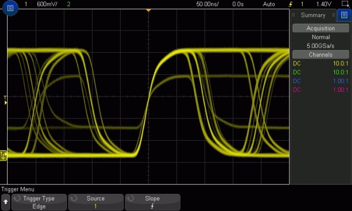
What if I am interested in one of these signals in particular? The rising edge trigger rule is not specific enough. That’s where advanced triggers come in: we need a more specifically defined rule to see exactly what we’re interested in!
Advanced Triggers
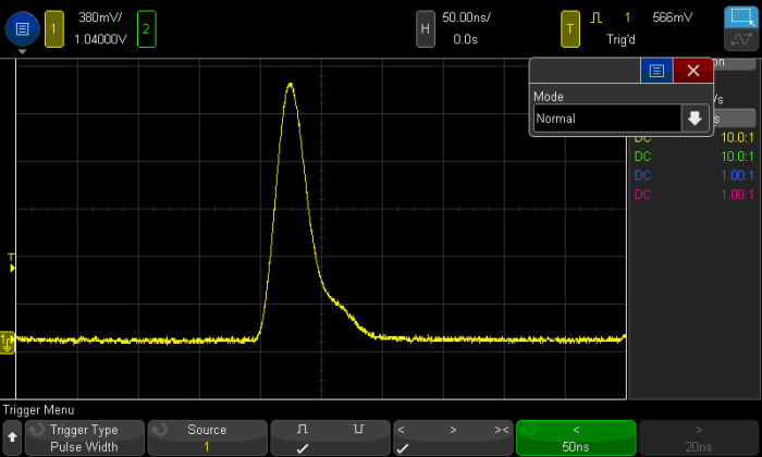
While the webcast goes over each trigger in detail, I’ll give an example of one here called pulse width trigger. With a pulse width trigger, we want the scope to take a photo if a signal rises and falls across a voltage threshold within a certain time restriction. In this signal, there is a clock with a pulse width of about 150 ns; you can see the signal crosses the trigger threshold in a rising direction, then again in a falling direction 150 ns later. The trigger threshold is visualized with the yellow T and arrow to the left of the screen, and timebase on top (50.00ns/division). But there is also a much smaller pulse the edge trigger is capturing, one that rises and falls again in under 50 ns:
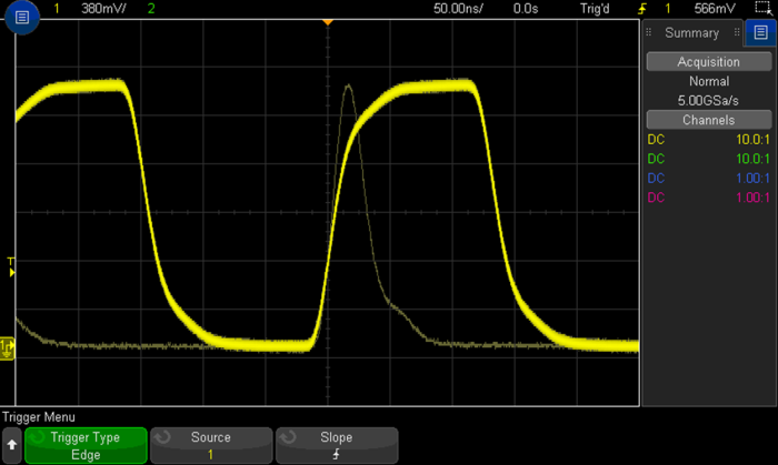
The basic edge trigger catches both. But by defining an advanced trigger, we can tell the scope to only take photos when the signal rises and falls across the trigger threshold in under 50 ns. Now, our picture is much more specific to what we want to troubleshoot:
Zone Triggering
Advanced triggers require some knowledge of the signal you’re testing, its shape and parametric qualities, as well as how to set the oscilloscope up properly. This is can be very difficult or nearly impossible for most scope users. Zone trigger was designed as a point and shoot system for isolating difficult signals within your design. This topic is covered in the webcast, or you can watch this video to learn more.
Serial Bus Triggers
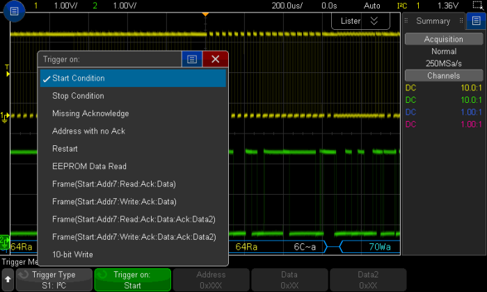
Keysight oscilloscopes also offer a suite of serial bus triggers. If you are working with an I2C bus and want to see when your device sends read commands to address 0x29, describing the shape of the signal as we did before simply will NOT work. We need a scope that is smart enough to translate the edge transitions in time to 1’s and 0’s and has knowledge of the I2C protocol. Here’s an example of the trigger capabilities for I2C:
Read more about how oscilloscopes can decode serial data and find the product datasheets in this blog article.
Trigger Modes and Coupling
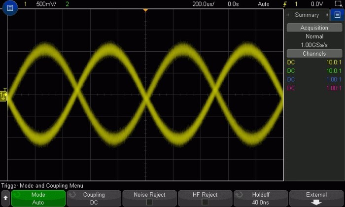
Life in the time domain is often a noisy one. And noise means triggering becomes difficult. For example, why is the scope triggering on rising and falling edges of the noisy signal below? If you zoom in, you’ll see that the falling edges of the sine wave contain small rising edges within it, that are large enough to qualify the oscilloscope to trigger. We cover all the different trigger modes and coupling techniques that can be used to make a more stable trigger in an unstable environment. You might also try bandwidth limiting, as described aptly by Melissa here!
Summary
Advanced triggers can be difficult to master, and times when you need them are few and far between. Zone trigger can take a lot of that headache away, which is great. Mastery of the advanced triggers in oscilloscopes can not only separate the true power users from the rest, but also take your ability to solve problems in complex designs to a whole new level. Isolating a problem signal allows you to dive deeper in your debug process and fix bugs faster. Check out the recorded Advanced Triggering and Signal Isolation webcast on our YouTube channel.